Access Port
Configuring VLANs on a Cisco 2960 switch, assigning access ports, and verifying network segmentation.
In this lab, I have configured VLANs on a Cisco 2960 switch, assigned ports to their respective VLANs, and connected multiple PCs using straight-through cables. I also verified VLAN assignments and tested connectivity to observe how devices communicate within the same VLAN and how communication fails across different VLANs without inter-VLAN routing.
Network Setup Overview
| Device | VLAN | IP Address | Port | Cable Type |
|---|---|---|---|---|
| PC0 | VLAN 10 (SALES) | 10.10.10.1 | Fa0/1 | Straight-through |
| PC1 | VLAN 10 (SALES) | 10.10.10.2 | Fa0/2 | Straight-through |
| PC2 | VLAN 20 (ENGINEERING) | 10.10.10.3 | Fa0/3 | Straight-through |
| PC3 | VLAN 20 (ENGINEERING) | 10.10.10.4 | Fa0/4 | Straight-through |
Core Device: Cisco 2960 Switch
Note: All PCs are connected directly to the switch using straight-through Ethernet cables.
Configuration Steps
-
Enable VLANs:
Switch(config)# vlan 10 Switch(config-vlan)# name SALES Switch(config)# vlan 20 Switch(config-vlan)# name Engineering -
Assign Access Ports to VLANs:
Switch(config)# interface fa0/1 Switch(config-if)# switchport mode access Switch(config-if)# switchport access vlan 10 Switch(config)# interface fa0/2 Switch(config-if)# switchport mode access Switch(config-if)# switchport access vlan 10 Switch(config)# interface range fa0/3 - 4 Switch(config-if-range)# switchport mode access Switch(config-if-range)# switchport access vlan 20 -
Shutdown Unused Ports:
Switch(config)# interface range fa0/5 - 24
Switch(config-if-range)# description Inactive ports
Switch(config-if-range)# shutdown

Switch(config)# interface range g0/1 - 2
Switch(config-if-range)# shutdown
Verification Commands
-
Check VLAN assignment:
Switch# show vlan brief -
Output:
VLAN Name                             Status    Ports
---- -------------------------------- --------- -------------------------------
1    default                          active    Fa0/5, Fa0/6, Fa0/7, Fa0/8
                                                Fa0/9, Fa0/10, Fa0/11, Fa0/12
                                                Fa0/13, Fa0/14, Fa0/15, Fa0/16
                                                Fa0/17, Fa0/18, Fa0/19, Fa0/20
                                                Fa0/21, Fa0/22, Fa0/23, Fa0/24
                                                Gig0/1, Gig0/2
10   SALES                            active    Fa0/1, Fa0/2
20   Engineering                      active    Fa0/3, Fa0/4
1002 fddi-default                     active
1003 token-ring-default               active
1004 fddinet-default                  active
1005 trnet-default                    active
Next Steps: Testing Network Connectivity
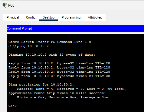
Pinging PC0 - PC1 (Sales VLAN: Same VLAN Communication)
Success — Communication succeeds as both PCs are in the Sales VLAN.
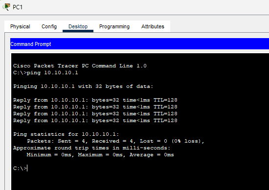
Pinging PC1 - PC0 (Sales VLAN: Same VLAN Communication)
Success — Same result as above, as both are in the Sales VLAN.
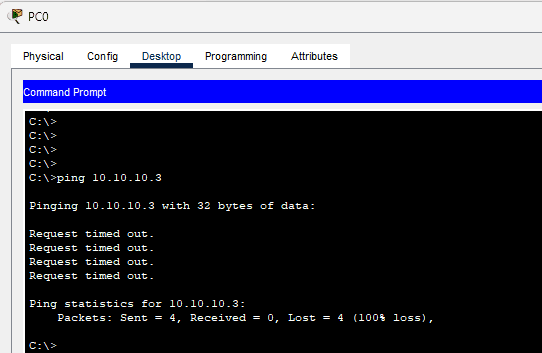
Pinging PC0 - PC2 (Sales - HR VLAN: Different VLANs)
Failed — Communication fails as the PCs are in different VLANs.
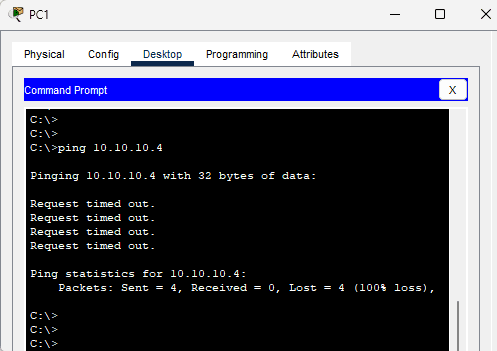
Pinging PC1 - PC3 (Sales - Engineering VLAN: Different VLANs)
Failed — Communication is blocked due to the PCs being in different VLANs.
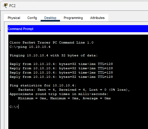
Pinging PC2 - PC3 (HR - Engineering VLAN: Same Network Configuration)
Success — These PCs can communicate as they are part of the HR and Engineering VLANs, which are properly routed.
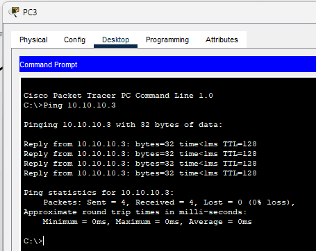
Pinging PC3 - PC2 (HR - Engineering VLAN: Same Network Configuration)
Success — As above, the PCs can ping each other successfully.
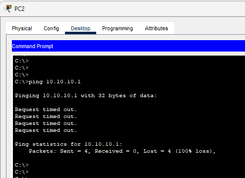
Pinging PC0 - PC2 (Sales - HR VLAN: Different VLANs)
Failed — Ping failed due to being on different VLANs.
Network Ping Results Overview
| Source | Destination | VLANs | Ping Result | Explanation |
|---|---|---|---|---|
| PC0 | PC1 | Sales VLAN | Success | Both PCs are in the same VLAN (Sales), so direct communication is possible. |
| PC0 | PC2 | Sales - HR VLAN | Failed | PCs in different VLANs, no routing configured. |
| PC1 | PC3 | Sales - Engineering VLAN | Failed | Communication blocked by VLAN separation, no inter-VLAN routing available. |
| PC2 | PC3 | HR - Engineering VLAN | Success | Routing enabled between HR and Engineering VLANs, successful communication. |
| PC0 | PC3 | Sales - Engineering VLAN | Failed | Devices in different VLANs; routing is required for communication. |
Visual Summary
| Ping Pair | VLAN Connection | Ping Outcome |
|---|---|---|
| PC0 - PC1 | Same VLAN (Sales VLAN) | Success |
| PC0 - PC2 | Different VLANs (Sales - HR) | Failed |
| PC1 - PC3 | Different VLANs (Sales - Engineering) | Failed |
| PC2 - PC3 | Different VLANs (HR - Engineering) | Success |